Game Boy Advance Wireless Adapter
Some people may be aware that I have played around with the GBA wireless adapter, indeed I’ve made one that works over the internet but unstably. The reason that I hadn’t made this post earlier is because I wanted to make it stable before releasing the code and writing it up. Alas, I haven’t had much motivation to continue, which is a shame given I got so close.
This is the first post of a planned two. In this first post I will be talking about how the wireless adapter works, and in the second I will talk about specifically how I did all this. The short version of that second post is using the PIO on Pi Picos.
The Wireless Adapter
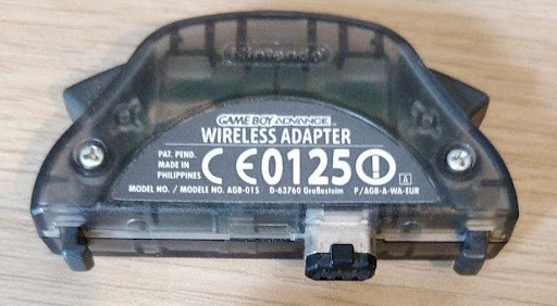
The Game Boy Advance Wireless Adapter
The wireless adapter is a piece of hardware that connects to the link cable port of a GBA that then communicates wirelessly with other adapters. It also contains a multibootable1 rom for playing games only one player has a copy of (although I am not aware of many games that use it, some NES classic games use this). However, the most notable games to use it is probably the Pokémon games Fire Red, Leaf Green and Emerald (Sapphire and Ruby do not have wireless adapter support)2.
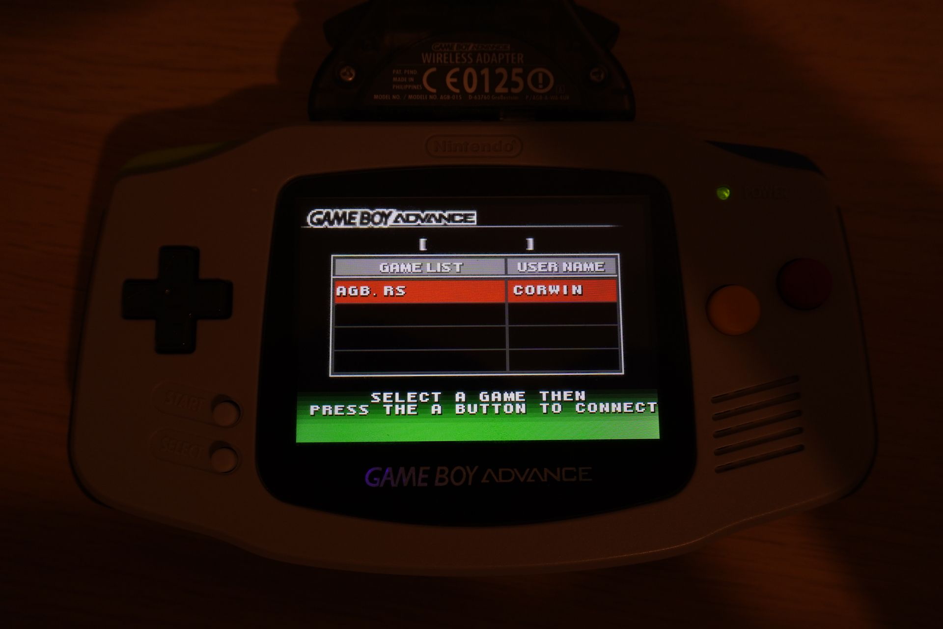
You can make this screen display any game
Communicating with the adapter
When I started, I used the following resources to start being able to talk with the wireless adapter:
- This Gist contains some details
- GBATEK has a section on the wireless adapter
- The Visual Boy Advance emulator has an implementation (although don’t use VBA!)
Pinout
The wireless adapter connects using the link cable port to the GBA. It uses
- 3.3V
- Serial In
- Serial out
- SD
- Clock
- Ground
which is all 6 of the pins. If you are going to mess with interfacing with the link cable yourself, make sure you know which pin is which. If you just want to use the wireless adapter as part of the GBA this isn’t relevant.
Serial Peripheral Interface
Broadly speaking the GBA communicates with the wireless adapter using the Serial Peripheral Interface (SPI), however it can be somewhat weird. In the case of the GBA this is a three or four wire protocol depending on how you count. The clock, two data wires, and what is normally chip select but operates more as a reset.
The reason you would have a chip select normally is because then you can reuse the other three wires across all the chips on your board and switch using the chip select. On the GBA we only have one other device on this bus, so a chip select isn’t really an apt term for it.

A logic analyser can be used to probe the link cable protocol between the GBA and a Wireless Adapter
I will break up the ways in which you communicate into three parts:
- Initialisation
- Commands
- Waiting for data
One thing to make note of is that when I have screenshots showing the logic analyser traces, these all come from Pokémon Emerald as it is what I had at the time I did a lot of this.
Initialisation
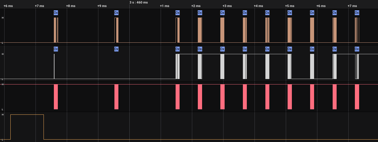
The initialisation sequence captured using a logic analyser
Before starting sending and receiving commands, a handshake with the adapter needs to be done. During this, the clocks runs at 256 kHz. Real games start this process by resetting the adapter.
To reset you take the reset line high. Most people refer to this as SD. You can see this in the figure.
After this the GBA sends a single command, although we will ignore this for now.
Next is the Nintendo Exchange.
Nintendo Exchange
The GBA and the adapter exchange the word “NINTENDO” with each other in quite a strange way.

GBA
sends 0x7FFF494E and wireless adapter sends 0x00000000.
The GBA here sends 0x7FFF494E, of this the relevant part is the 0x494E. If
we look up what the bytes 0x49, 0x4E are you will find them to be the letters
NI. As exchanges happen simultaneously, at this point the adapter doesn’t know
what to respond with and so responds with all zeros.

GBA sends 0xFFFF494E and wireless adapter sends 0x494EB6B1.
Next the GBA sends 0xFFFF494E and now the wireless adapter does respond and
responds with 0x494EB6B1. I can assure you there is a pattern here:
- GBA:
- Two most significant bytes are the inverse of the adapters previous most significant bytes.
- Two least significant bytes are the GBA’s own data.
- Adapter:
- Two least significant bytes are the inverse of the GBA’s previous least significant bytes.
- Two most significant bytes are the adapters own data.
The “own” data are the bytes of the string “NINTENDO”, and you advance to the next pair when the most significant bytes equal the inverse of the least significant bytes.
Following these rules the transfer looks like
| GBA | Adapter |
|---|---|
0x7FFF494E |
0x00000000 |
0xFFFF494E |
0x494EB6B1 |
0xB6B1494E |
0x494EB6B1 |
0xB6B1544E |
0x544EB6B1 |
0xABB1544E |
0x544EABB1 |
0xABB14E45 |
0x4E45ABB1 |
0xB1BA4E45 |
0x4E45B1BA |
0xB1BA4F44 |
0x4F44B1BA |
0xB0BB4F44 |
0x4F44B0BB |
0xB0BB8001 |
0x8001B0BB |
Although note that due to the rules, the first few transfers may contain some junk data and be different to this in practice. And after this, you can start sending commands.
Commands

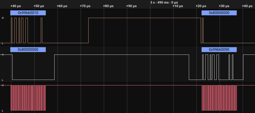
A command being sent by the GBA and acknowledged by the adapter
Commands are how you tell the adapter to do things. When in command mode the clock operates at 2 mHz. Some examples of commands include connect to adapter, send message, and receive message. All commands follow the same form:
-
Command
The command is a 32 bit value of the form
0x9966LLCC:- LL
- The length of the data payload in number of 32 bit values. For example
here it is
0x01, so one value is transmitted after this.
- The length of the data payload in number of 32 bit values. For example
here it is
- CC
- The command type, there are a bunch of these! In this case the command
type is
0x17.
- The command type, there are a bunch of these! In this case the command
type is
- LL
-
Data
All the data along with the command, must transmit the number given in the command
-
Acknowledge
The adapter responds with a command, the length is the number of 32 bit values and the command type is always what you send +
0x80. In this case the length is zero and the command is0x17+0x80=0x97.If you sent an invalid command, you instead get
0x996601eeas response 3. -
Response
The data that the adapter responds with. Equal to the length given in the acknowledgement.
-
Ready
In the figure, you’ll see that after exchanging any 32 bit value using SPI, some out of clock communication happens. This is the GBA and the Adapter signalling to each other that they are ready to communicate. This happens over the following stages:
- The GBA goes low as soon as it can
- The adapter goes high.
- The GBA goes high.
- The adapter goes low when it’s ready.
- The GBA goes low when it’s ready.
- The GBA starts a transfer, clock starts pulsing, and both sides exchange the next 32 bit value.
Whenever either side expects something to be sent from the other (as SPI is
always dual direction, although one side is often not used), the value
0x80000000 is used.
The adapter starts listening for an instruction after a timeout of around 800 micro seconds 3.
List of commands
Finish Initialisation - 0x10 and 0x3d
-
Send length: 0, Response length: 0
-
First thing to be called after finishing the initialisation sequence.
Broadcast - 0x16

-
Send length: 6, response length: 0
-
The data to be broadcast out to all adapters. Examples of use include the union room, broadcasting game name and username in download play, and the username in direct multiplayer in Pokémon.
-
What the bytes mean can be seen in this figure from 3.
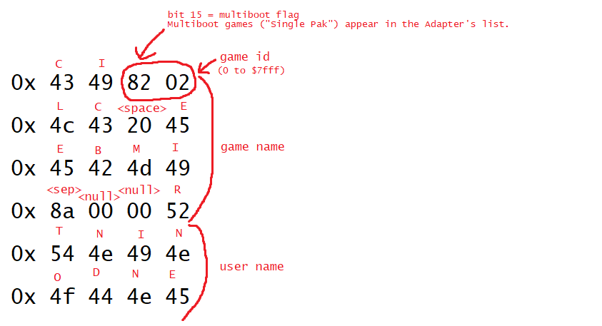
The meaning of the bytes in a broadcast transmission.
Start Host - 0x19
-
Send length: 0, response length: 0
-
This uses the broadcast data given by the broadcast command and actually does the broadcasting.
BroadcastRead - 0x1c -> 0x1d -> 0x1e

- This section broadly from 3.
- Broadcast reads formed from three parts, Start, Read, End with
0x1c,0x1d, and0x1erespectively. - First send start,
0x1c:- Send length: 0, response length: 0(?).
- This will finish instantly, you should wait 1 second or so (smaller waits are possible, for example ~160ms) 3.
- Then broadcast read,
0x1d:- Send length: 0, response length: 7 * number of broadcasts
- All currently broadcasting devices are returned here along with an ID at the start of each.
- IDs I’ve observed have been 16 bits.
- IDs randomly generated every broadcast 3.
- Then finish,
0x1e:
Setup - 0x17

-
Send length: 1, response length: 0
-
Games set this to
0x003C0420. Not sure what affect this has4.
ConnectedAdapters - 0x1a
-
Send length: 0, response length: 0+
- Responds with the IDs of connected adapters3. (I expect these to each be in a separate 32 bit value).
- Disconnecting by, for example, turning the console off won’t cause a disconnect here. Timeouts need to be handled separately3.
Connect - 0x1f

-
Send length: 1, response length: 0
-
Send the ID of the adapter you want to connect to from BroadcastRead.
IsFinishedConnect - 0x20

-
Send length: 0, response length: 1
- If the connection is finished:
- Responds with 16 bit ID as the lower 16 bits and client number as bits 17 and 183.
- Two bits allows 4 different values, this means that 5 adapters can be connected at maximum (4 clients + 1 host).
- Otherwise
0x01000000.
FinishConnection - 0x21

-
Send length: 0, response length: 1
-
Called after IsFinishedConnect, responds with the same ID as in that response and zeroes in the high 16 bits3.
SendData - 0x24
-
Send length: N, response length: 0
-
The first value contains a header which depends on the number of bytes (not values) to send3.
SendDataWait - 0x25

-
Send length: N, response length: 0
- The same as SendData but with the additional effect of Wait
- See Waiting for more details on this.
ReceiveData - 0x26

-
Send length: 0, response length: N
-
A single header is included as the first value of the response. I believe this is the headers from the connected adapters orred together.
Wait - 0x27
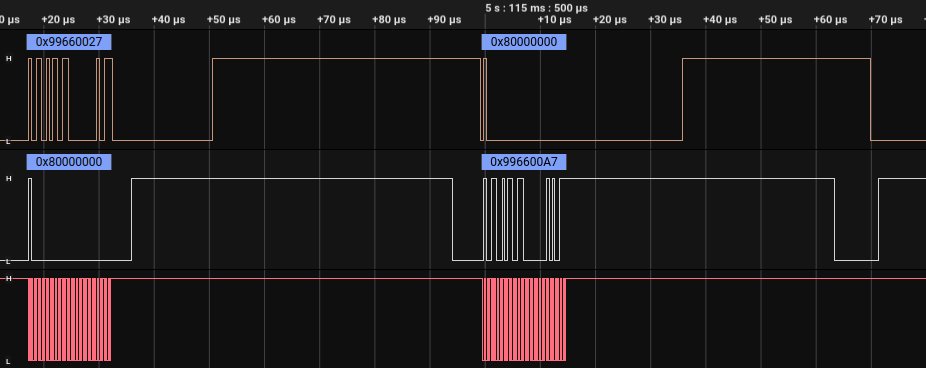
-
Send length: 0, response length: 0
-
See Waiting for more details on this.
List of commands that I don’t quite know the meaning of 4
0x11
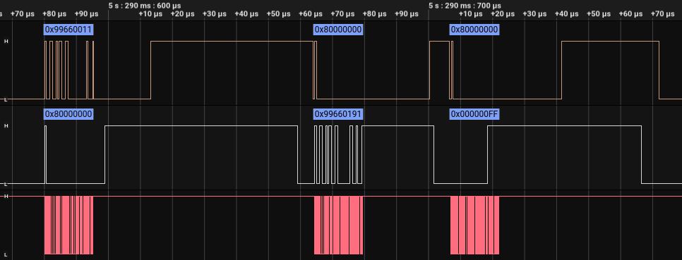
-
Send length: 0, response length: 1
- I think this is signal level of the adapters.
- I generally set this to
0xFF. - If my theory is correct then up to 3 bytes could be included each referring to the signal strength of the potentially connected 3 devices.
0x13
-
Send length: 0, response length: 1
-
I generally set the response to
0x00.
0x30

-
Send length 1, reponse length: 0
- This is very important, is the end of every connection I’ve seen.
- Send is always
0x1. - Appears to reset the adapter in some way:
- Disconnects
- Stops broadcasting
- Clears buffers?4
Waiting
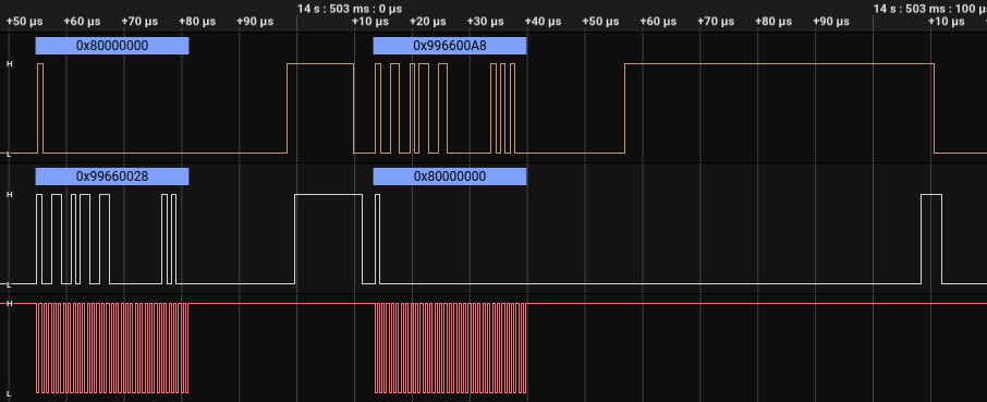
- After either SendDataWait or Wait, clock control switches to the wireless adapter.
- Once the adapter has something to tell the GBA about, the adapter sends a
command to the GBA,
0x99660028. - These transfers are dealt with in much the same way as before but with the roles of the GBA and the adapter reversed, see the figure!
- The GBA then sends the response back,
0x996600A8as0x28+0x80=0xA8. - After this, control of the clock returns to the GBA, and it can start sending commands back again. For example this might be receiving the command sent by the other device using ReceiveData.
- This will timeout after ~500ms. The adapter will send
0x99660027and the GBA should respond accordingly3.
I know more!
If you know any extra details about the wireless adapter, get in touch!. For specific details I’ve left footnotes around if you happen to know that piece of information4.
Update:
- The contents of this post have been expanded upon in rodri042/gba-link-connection/blob/master/docs/wireless_adapter.md, which I will incorporate with reference 3.
-
Multiboot is what we call a rom that can be booted over link cable. This can be used for something akin to download play software for the DS. ↩︎
-
rodri042/gba-link-connection/blob/master/docs/wireless_adapter.md ↩︎ ↩︎2 ↩︎3 ↩︎4 ↩︎5 ↩︎6 ↩︎7 ↩︎8 ↩︎9 ↩︎10 ↩︎11 ↩︎12 ↩︎13 ↩︎14 ↩︎15
-
Send me an email if you know more about this ↩︎ ↩︎2 ↩︎3 ↩︎4